
A production line rarely stays with one PLC family forever. A Siemens controller may run the main machine while a packaging unit, utility skid, or older subsystem exposes its data over Modbus TCP. The SCADA system then needs a separate driver, connection, and addressing model for every source.
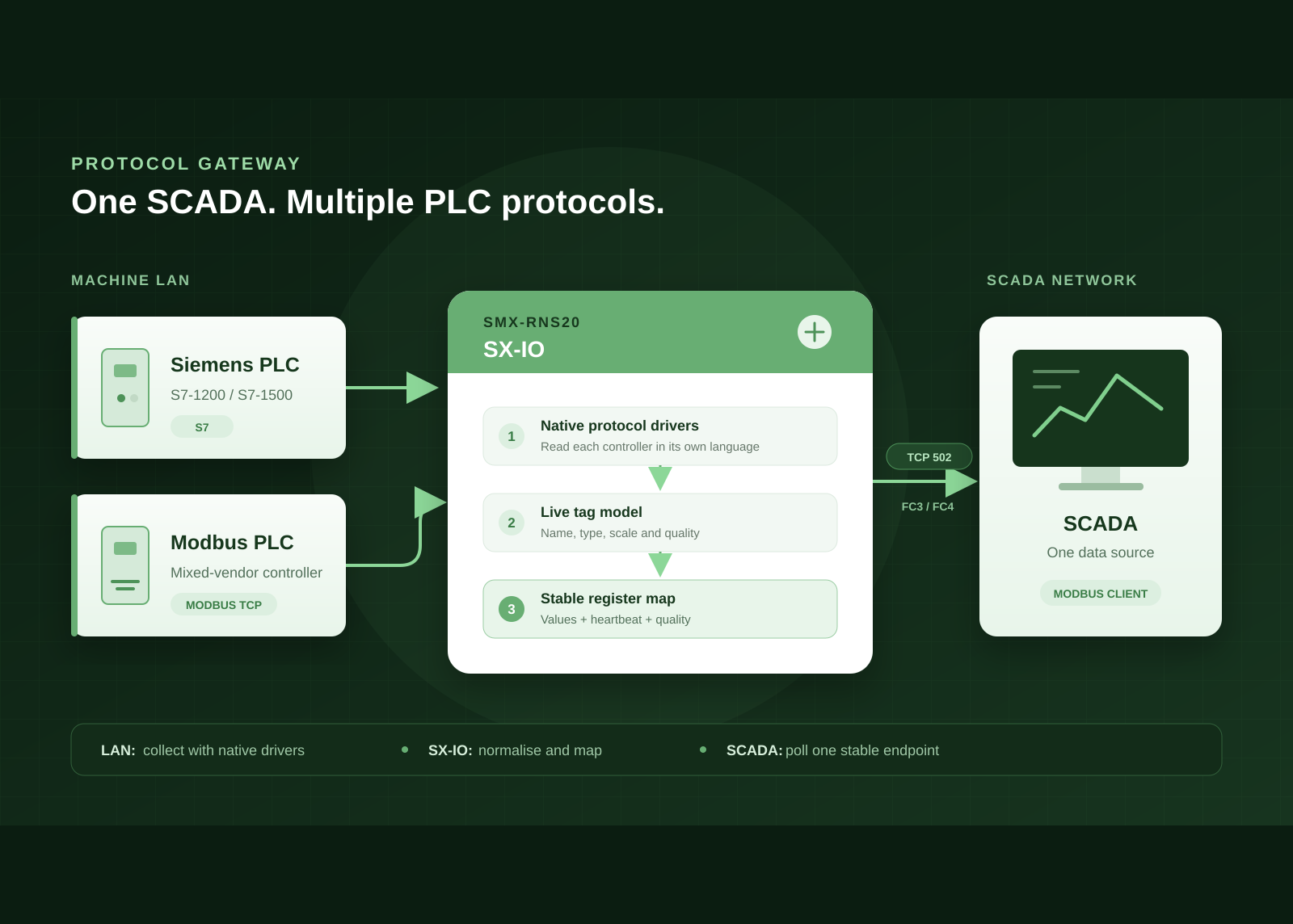
A protocol gateway gives the SCADA side a simpler contract. In this example, SMX-RNS20 reads both PLCs on the machine LAN through SX-IO, converts the selected values into a common tag model, and publishes them through one Modbus TCP server on the SCADA-facing network.
The Example Architecture
The machine LAN contains two independent data sources: a Siemens S7 PLC at 192.168.10.10 and a Modbus TCP PLC at 192.168.10.20. SX-IO connects to each device through its native driver and polls only the values needed by SCADA.
On the other side, SCADA has a single connection: the SMX-RNS20 address on the SCADA-facing network, TCP port 502. It does not need an S7 driver and it does not connect directly to either PLC. All protocol-specific addressing stays inside SX-IO.
WAN does not mean public Internet here. It is the SMX-RNS20 interface connected to the plant or SCADA network. Modbus TCP port 502 should never be exposed directly to the Internet.
Why This Is More Than a Simple Converter
A basic protocol converter translates requests as they arrive. SX-IO first builds its own live tag model. That extra layer is what makes the SCADA interface predictable:
The Siemens PLC is read with S7 addressing; the second PLC is read with Modbus function codes and registers.
Source addresses are converted into a common model with names, data types, scaling and quality.
Only selected tags are published. Their addresses stay fixed even when other mappings are later removed.
Step 1: Build the Tag Model
Add one driver for each PLC, then define the source address and type of each value. A small example could look like this:
| SX-IO tag | Source | Address | Type |
|---|---|---|---|
| line_speed | Siemens S7 | DB1,REAL4 | Float |
| tank_level | Modbus TCP | FC3,0 | UInt16 |
| pump_running | Modbus TCP | FC3,10,3 | Boolean |
On S7-1200 and S7-1500 controllers, PUT/GET communication must be permitted. Data blocks also need absolute addressing; an optimised DB has no fixed byte layout. I, Q and M areas remain absolutely addressable.
Step 2: Create a Stable Register Map
The SX-IO Modbus TCP server uses an explicit map. Adding a tag can automatically select the next free address, but the saved address does not later shift. If a mapping is deleted, it leaves a gap instead of silently changing every SCADA address after it.
| Register | Published value | Format | Width |
|---|---|---|---|
| 0–1 | line_speed | Float | 2 registers |
| 2 | tank_level | UInt16 × 10 | 1 register |
| 3 | pump_running | Bool | 1 register |
| 1000 | Heartbeat | UInt16 | 1 register |
| 1001 | Quality bits 0–15 | Bit field | 1 register |
SX-IO uses zero-based register addresses. Some SCADA packages display register 0 as holding register 40001. Confirm the convention in the SCADA driver before commissioning.
Step 3: Configure the SCADA Connection
Point the SCADA Modbus TCP client to the SMX-RNS20 address on the SCADA-facing network and use TCP port 502. The same published values can be read as holding registers with FC3 or input registers with FC4. Match the data format, scale, byte order and word order to the map defined in SX-IO.
This interface is intentionally read-oriented: SCADA receives the current values but does not write control commands back through the gateway. Machine control remains in the PLC, where its timing, interlocks and safety logic belong.
Do Not Read Values Without Their Health
Modbus registers alone cannot say whether a zero is a real process value or the result of a failed PLC read. SX-IO therefore reserves two parts of the register map for health:
Register 1000 — heartbeat. It increments on each SX-IO polling cycle. A counter that stops changing indicates that the published view is no longer refreshing.
Registers 1001 onward — quality. Each mapped tag has one quality bit, ordered by its register address. A set bit means the current source reading is good.
If an upstream value cannot be read, its data registers are published as zero and its quality bit is cleared. SCADA should evaluate both the quality bit and heartbeat instead of treating every numeric value as valid.
What Happens During a Network Failure?
The affected tags change to bad quality. Collection from the other PLC and the rest of SX-IO continue to operate.
SX-IO continues local acquisition, alarming, trending and archiving. When the connection returns, Modbus exposes the current snapshot again.
Modbus TCP is a live register interface, not a historical replay channel. Retrieve stored records through a historian-oriented integration such as SQL, MQTT or an API.
Treat Modbus as a Protected OT Service
Classic Modbus TCP has no built-in authentication or encryption. Place the SCADA-facing interface in a controlled plant network, allow only the SCADA host to reach TCP 502, and block that port from every other network zone.
For remote access, use a separate encrypted access path. Do not publish Modbus TCP directly on a public IP. The Modbus Organization also uses the current terms client and server; older SCADA software may still label the same roles master and slave.
When This Pattern Fits
It is not a replacement for safety communication, deterministic control, or an historian interface. Used within those boundaries, SMX-RNS20 turns a mixed PLC network into one clean and maintainable Modbus TCP data source for SCADA.